 |
High School
Teachers at CERN |
||
| WWW.CERN.CH |  |
||
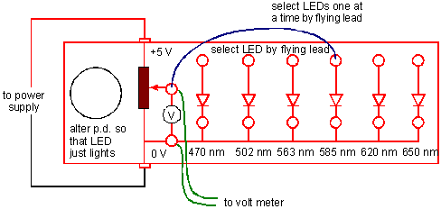
Building the array of LEDsWhat it is for Used in chapter 7 to make the connection between the frequency at which a photon is emitted and the energy carried by that photon. Measurements are made of the minimum p.d. required to just turn an LED on, and of the wavelength of light from it. The wavelength may be better taken direct from the manufacturer's specification. Each LED emits photons of one characteristic frequency, specified in many catalogues by the peak wavelength emitted by the LED. You need a wide range of wavelengths, fairly evenly spaced, so as to get a reasonable graph of p.d. against frequency or wavelength. You may find a wider range of LEDs available at lower cost than when this design was first produced, if so then exceeding the range suggested is fine; reducing that range does not yield a reliable graph. To measure the energy carried by each photon students will need to be able to measure the pd applied across each LED in turn. Students then plot energy / frequency. So it may be useful to mark the peak frequencies or wavelengths emitted by the LEDs on the apparatus. How to make it The requirement is to be able to apply a variable pd, 0-3 V, across a series of LEDs, one at a time in turn. 5 LEDs is sufficient. Increasing the range of frequencies is more important than adding more LEDs. We suggest that the LEDs be mounted in plastic ducting, a 150 mm length of 40 mm by 25 mm proved sufficient to neatly mount all the components.
Variations are, of course possible. You may choose not to have sockets to measure the current through the LEDs (as the photographs have), or perhaps to have only one return wire so that the LEDs come on one after another as the pd is increased. A suitable protective resistor (roughly equal in value to the resistance of the shortest wavelength LED) in series with the wiper arm of the potentiometer will prevent applying too much pd across the LEDs. Important features
|
| © CERN and High School Teachers Programme at CERN | Last modified: 28 June 2002 |